
Overview
This page gives a technical overview of PSI5. For more detailed information, please refer to the current version of the specification or contact the PSI5 steering committee.
Automotive Sensor Interfaces
PSI5 is designed to meet the requirements of a universal, highly reliable automotive sensor interface at the lowest possible implementation costs. PSI 5 was originally developed for the use in airbag applications. However, the mid-range data transmission rate of 125 kbps covers most of the automotive sensor applications and offers enough bandwidth for a lot of multi-channel sensor configurations.
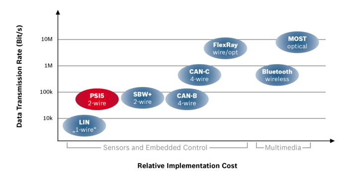
The usage of just two unshielded wires for both data communication and power supply reduces the expenses for cable harness & connector pins and thus leads to minimum overall system costs. PSI5 is covering the “low-end” automotive sensor interface segment. Limitations are the unidirectional data transmission, the fixed 125kbps data rate and a maximum possible sensor quiescent current of approximately 50mA. The “high-end” interface segment is covered by CAN and FlexRay.
System Setup
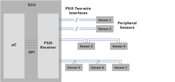
The example above shows a typical system setup with a point-to-point connection of the sensors 1 and 2 and a bus configuration of the sensors 3 and 4.
Data Transmission / Physical Layer
Sensor data is transmitted by current modulation on the supply lines:
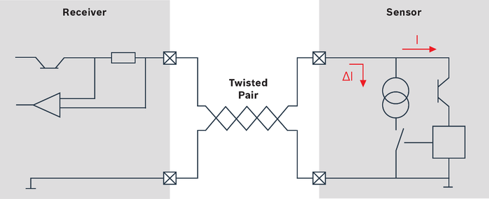
The receiver provides a pre-regulated voltage to the sensor and monitors the current on the supply lines e.g. by means of a shunt resistor. A logic “low” is represented by the quiescent current of the sensor. The sensors mark a logic “high” level by sinking an additional 20 mA current resulting in a higher voltage drop at the receiver’s shunt resistor. The relatively high signal current in combination with the low impedance of the system leads to an extremely high robustness of the data transmission against radiated immission and thus to an excellent EMC behavior.
Bit Coding / Data Link Layer
Manchester coding is used for data transmission. A logical "0" is represented by a rising slope and a logical "1" by a falling slope of the sending current in the middle of each bit.
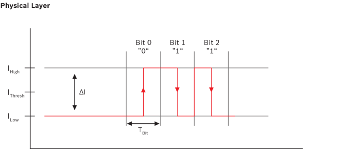
Advantages of the “Manchester Code” are the constant current mean value during data transmission and the tolerance against system clock deviations. PSI5 uses data frames with two start bits, 8…24 data bits and a parity bit or an optional three bit CRC.
Operation modes
PSI5 provides both asynchronous and synchronous data transmission and supports time multiplexed multi-channel operation modes for sensor clusters. In the asynchronous operation mode each sensor is connected to the ECU by two separate wires and transmits its data periodically. Timing and repetition rate of the data transmission are controlled by the sensor. Synchronous operation allows a communication timing control by the ECU. This mode can be optionally used for point-to-point configurations and is mandatory for bus modes. Timing and access control are realized by two different voltage levels generated by the ECU.
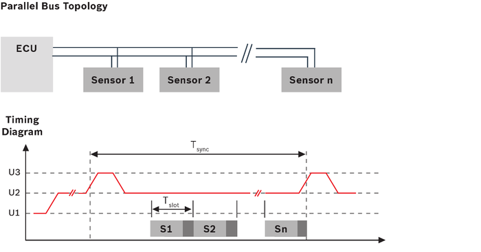
Each data transmission period is initiated by a voltage synchronization signal from the ECU to the sensors. After having received the synchronization signal each sensor starts transmitting its data with the corresponding time shift in the assigned time slot. An individual numbering of the sensors is required. In a sensor cluster configuration one physical sensor may contain two or more logical channels. Examples could be a two channel acceleration sensor or a combined temperature and pressure sensor. Sensor cluster and multi-channel operation modes can be combined with both asynchronous and synchronous data transmission and with different bus configurations.
